Jacobs Ignition User Manual

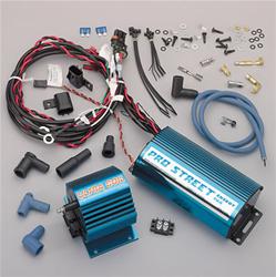
ProStreet Ultra Team IgnitionSystem InstallationHere are the pics and install notes from theinstallation of a Jacob's Electronics Pro Street Ultra Team ignition system on my 1997Highrider with L35 4.3 Liter V-6 engine. Jacob's suggested that I use the Pro Street unitinstead of the Mileage Master due to the other modifications I have made to my truck. Ifyou call them and tell them what you have done to your truck they will recommend theproper set for you.Before you read through this all - an overallimpression of the system is that it does require a good amount of money, work, andpatience to get it working properly. If you want a simple bolt-on in 1/2 an hour thisisn't for you, and you might as well skip the following notes. However, once you get itworking, the thing rules and the truck runs awesome.The total cost, including shipping, was $420.Jacob's list this set for over $700, but I shopped around and ended up getting a demo thatthey had used for a magazine photo shoot - or so they said. It had never been powered up,but since it was opened they gave me a deal on the price and a full warranty. I think thatif you haggle with them long enough, anyone could probably get them down to around $400.1.
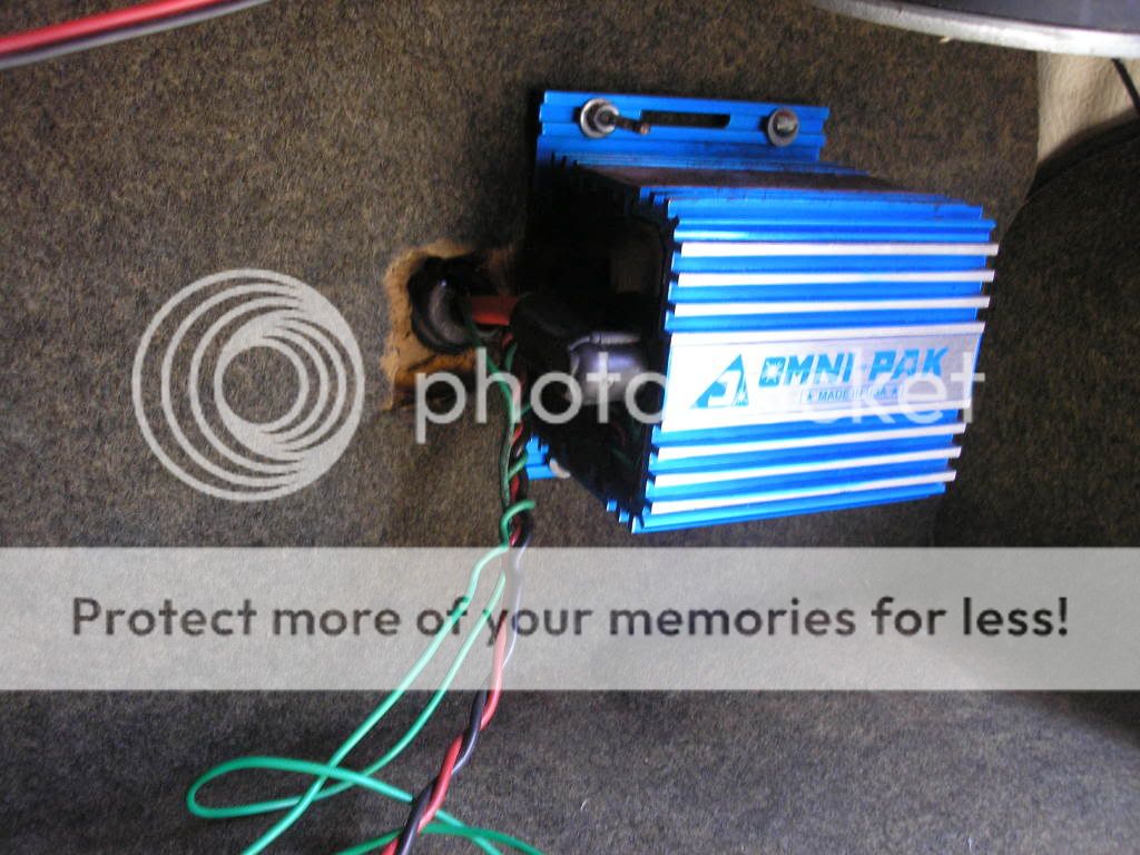
The first step wasto mount the Pro Street Computer Module. The only room I could find under the hood tomount the computer module was on top of the heater core and fan housing. This areaprovides several advantages in that no existing components had to be removed or relocatedin order to mount the module. The module fits snugly between the heater core, fan housing,and the rubber hood seal at the back. I ground down the corner of the module that sits onthe fan housing so that it wouldn't wear through.
I then used the four screws suppliedwith the unit to secure the module to the heater core. Before I predrilled, I took theheater core apart far enough to ensure that I wouldn't be drilling or screwing intoanything that could be damaged. The four screws are all along one side, but with the waythe unit is supported and held in place by the hood seal on the back, this is a verystable mount.


Here are several pictures of the installed computer module.2. The next step wasto install the new Ultra Coil. The only space I found for mounting this was on thedriver's side fender well. It took some creative twisting and turning to get it in therepast the brake lines, but once in place it fits fine. I drilled holes into the fender andused the four screws Jacob's supplied to mount it to the fender. One problem I encounteredhere was that when I closed the hood, the vacuum reservoir hit the coil and wouldn't letthe hood close. In order to solve this, I removed the reservoir and its little mountingbracket that was attached to the hood.
I then took the mounting bracket and attachedit to the plastic wire guard above the brake booster. I then mounted the reservoir to theold bracket in the new location, ran the vacuum lines in a safe location and everythingfit great. The last step is to run the new wire from the Ultra Coil to the stockdistributor. Here are two pictures of the installed Ultra Coil and relocated vacuumreservoir.3.
The third step wasto install the secondary trigger. It is the small blue box you can see mounted on thefirewall with the 'plug wire' going from it to the top of the stock coil. Thisis the device that converts the OEM spark signal into a signal that is fed to the newcoil. The new coil uses this as its timing signal.Another important function of the secondary triggeris to tell the coil and computer module when to power up. In order to do this, you musttap into the positive wire coming into the stock coil.
Double check that this wire is deadwhen the key is in the 'off' position and live when the key is in the'run' and in the 'start' positions. If the wire is not live when thekey is in the 'start' position, the trigger will not tell the coil to fire untilafter you let go of the key possibly starting the engine at that point.4.
The fourth step wasto install the new Autolite copper core spark plugs gapped at.070 up from the.060 stocksetting. Once this was completed, I also installed the new plug wires supplied by Jacob'sas part of the Ultra Team kit. Here is a picture showing the new wires going through thestock wire locators.
They are bigger than OEM wires so it takes some effort to get theminto the old locators.5. The final step wasto install the wiring accessories for the computer module. Jacob's sells these in a bundlethat costs $100. After some research, I discovered that I could make my own from RadioShack parts for around $11. There is a row of small terminals on the side of the computermodule.
One of these is a ground. In order to activate the different features, all youhave to do is ground the other terminals to the one ground terminal. I hooked up three ofthe features on my truck.A. The first featurewas a full throttle switch which puts the computer and coil into 'high output'65,000 volt mode for a limited amount of time. Jacob's says to mount this switch under thegas pedal, but I put mine right on the throttle body so that when you are at wide openthrottle, the throttle linkage makes the switch which grounds that terminal on thecomputer module, sending it into high output mode. I had to custom fabricate a bracketwhich I plan on painting black the next time I have a chance.
Here are a few pics of thebracket and switch.B. The second featurethat I installed was a hidden security switch. This lets you disable the ignition when youwill be away from the vehicle. It allows you to start the truck and drive it for severalfeet before it begins misfiring select cylinders. This continues for a few more seconds atwhich time it misfires more and more cylinders until the engine dies.
It sort of seemslike you are running out of gas. Then when you try to start the truck again, the wholesystem is disabled and won't allow the engine to start.
Jacobs Ignition User Manual Pdf
I'd show picture of the switch andtell how to disable this function, but that would sort of defeat the whole'security' purpose of this feature.C. The third featurewas a diagnostic LED light that tells you what the computer module is doing. I ran thewires up through the dash and installed the light in the upper right corner near the gaugecluster. The light is on steady during normal operation.